






Press play to start listening
A few years ago, I worked on ArcForce, a mobile 3v3 hero shooter set in a colorful and futuristic world. The artistic goals for this mobile project were particularly ambitious since we aimed at pushing graphical limits as far as we reasonably could and trying to achieve the sensation of playing on a console, despite having an average-level Android device.
That created an interesting production problem. This project was developed using an international remote workforce; therefore, we could not rely on everyone developing the same assumptions through everyday conversations. An artist could create an amazing asset that cost twice as much as initially estimated. Another person may have had a completely different understanding of what a certain limitation entailed. Such factors seemed trivial on their own, but they multiplied once all elements were put together.
As an Associate Art Director, my position entailed establishing not only the artistic direction, but also the technical rules behind it: guidelines that gave artists enough freedom to push the visuals while setting the necessary parameters within which creativity would operate. These included standards that ensured that all created assets could seamlessly merge to create a unified world.
This is where conventional budget allocations for mobile game art started to feel insufficient. Indeed, what triangle limit does your prop have? Should your texture be limited to 2K? How many material sections are acceptable? You need those numbers, but on their own they do not tell you enough. Buildings cover entire screens. Large generators may cover a third of the display area, while a drainpipe may never be more than a few percent of it. Applying uniform constraints across these elements is impractical.
When it comes to environment art, however, I took my starting point from two other questions: How big can the content get on the screen? What will happen to it when it gets smaller because of the distance? Screen size gives me an indication of how the content should be made. Distance indicates the information I can safely remove after that.
Here, my scope is static environment art created in Unreal Engine using traditional LOD techniques for Static Meshes and relying mostly on baked lighting. Instead of providing universal budgets for mobile, this article will focus on how to make these decisions about geometry, textures, materials, draw calls, and memory.
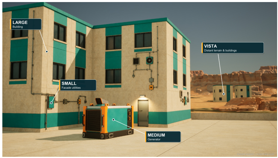
Classify Content by Maximum Screen Size.
Before setting content rules, we still needed the standard constraints: lowest supported device, target resolution, frame rate, memory capacity, and quality levels. However, after this had been decided, no uniform rules regarding the number of triangles, textures, etc. were applied to every environment asset. Instead, environment content was divided into four general categories:
- Large – content significantly larger than a character: walls, buildings, roads, grounds, cliffs, and bridges.
- Medium – content roughly equal to a character in terms of size: cars, shipping containers, large generators, sculptures, and other similar assets.
- Small – content significantly smaller than a character: pipes, vents, brackets, utility boxes, and other secondary elements.
- Vista – far background content that could not be reached by the player: skyline buildings, unreachable industrial complexes, mountains, or other cityscape segments.
These categories did not depend on the type of the asset but on its likely screen presence. No specific threshold in terms of the percentage of screen coverage was used, but rather, with ArcForce’s fairly consistent third-person camera, character scale was used as a guide, which was easy to assess during production time. Vista content was an exception, as it could not be reached by the player.
This straightforward classification allowed the team to have a common ground for all decision-making regarding authoring, LOD, materials, and optimization. The following paragraphs will discuss in detail how each of these types was authored and optimized.
Build each category for how it will be seen
Large: Preserve Detail Up Close, Simplify at Distance
In terms of visual fidelity, development efficiency, memory requirements, and computational cost, assets of large sizes tend to demonstrate this compromise most vividly. As a general rule, if an asset can be approached closely by the player, it should contain a sufficient level of textural and geometrical detail for close observation without loss of fidelity.
From this perspective, all feasible methods lie somewhere between two extremes. The former involves creating a massive unique texture assigned to a material applied once to a surface. While the material itself is relatively easy to implement, it is difficult to scale across very large surfaces: maintaining good texel density across an entire facade can quickly require large textures, consuming more memory. In addition, unique textures cannot easily be reused across different buildings, and keeping many independently authored buildings visually consistent becomes a production problem.
The second technique is a library of reusable tiled materials such as brick, concrete, architectural trim elements, etc. In terms of production and memory cost, this approach suited us better, as the same materials were reusable in different buildings, texel density could stay constant, and the library helped us to create a cohesive visual style.
In the case of the second technique, the cost becomes apparent during runtime. Creation of a facade using several material sections may result in a higher draw call cost for rendering the mesh as well as a higher geometry cost of a close-range version due to the necessity of additional geometry detail. In the case of ArcForce, we used both techniques:
- Close range – tiled reusable materials, several material sections, and detailed geometry
- Distance – single low-resolution baked texture, one material section, simplified geometry
Once the player moved far enough away, the quality gain resulting from the use of tiled materials and detailed geometry became too small to justify the additional cost. Thus, for the distant LOD, we baked those materials into one low-resolution texture and aggressively simplified the geometry. This reduced geometry and material sections and, in our setup, draw calls, while preserving the information that still mattered at distance.
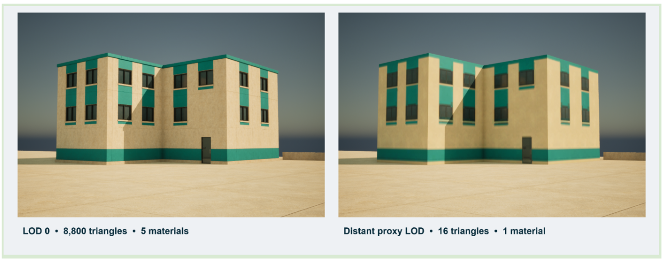
We aimed to switch to this LOD model as close as we possibly could to the camera without making the transition noticeable during gameplay. Thus, the key requirement was maintaining the primary silhouette and major surface planes of the original mesh. Smaller details could disappear; however, any changes to larger surfaces’ positions, orientations, or geometry could noticeably alter the silhouette and shading, making the LOD switch much easier to notice.
The Medium: One Asset, One Texture Set
For medium assets, another principle applied was quite straightforward: one asset equals one texture set. Medium objects such as cars, cargo containers, generators, or sculptures are large enough to read clearly as complete objects, but small enough that a single texture set can usually provide the resolution needed without the tiled-material setup used for Large assets.
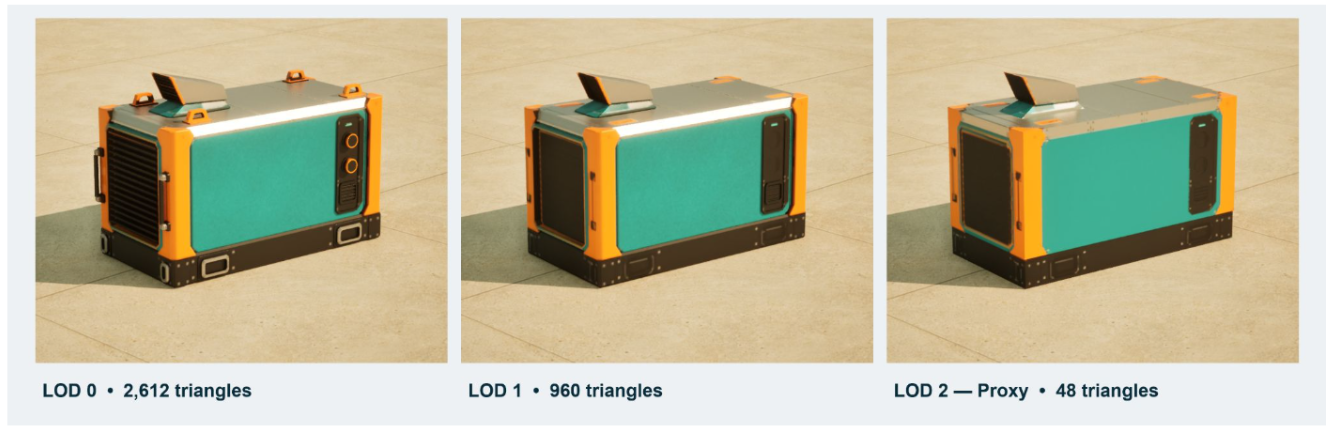
The texture strategy can therefore remain largely unchanged through the LOD chain: as the asset gets smaller on screen, mipmaps handle the decreasing texture footprint, while decreasing detail levels allow for pruning geometry that no longer contributes.
Handles, hinges, screws, bolts, and small recesses get stripped away first in the process, since the silhouette remains the essential defining element for each model.
Thus, it becomes possible to remove unnecessary elements while maintaining core geometries.
Small: Build details in layers
The small elements you create are precisely those that bring that extra level of depth needed to complete a scene. Your model may be entirely composed of walls made out of bricks or concrete tiles. But adding pipes, ventilation grilles, brackets, wires, and utility boxes can give your structure that extra depth.
Of course, these individual components do not need many details themselves. They are supposed to provide support to the larger objects they accompany. Their value comes from quantity – and that is also where the performance problem appears. A single pipe or vent is cheap; dozens of them across every building are not.
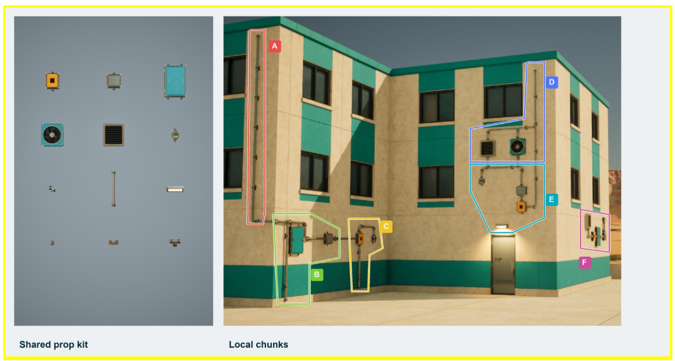
These props were created as collections for specific locations/arenas, with each collection sharing one atlased texture set and one material. Therefore, reusing became incredibly simple, while having the same material configuration gave us more freedom to combine them efficiently later.
Art was still tasked with placing individual props within the level editor. After successful placement was achieved, however, multiple nearby props could be merged into local chunks. An example would be combining ten different pieces of dressing in one section of the wall into a single merged mesh using the shared material.
The question of the ideal chunk sizes deserves discussion. The merging process helps to minimise the number of processed individual items and, when the geometry shares a suitable material setup, can also reduce draw-call overhead.
At the same time, overly large combined chunks produce large bounding boxes, making the entire mesh less efficient to cull from render pipelines. In turn, insufficiently large sizes fail to provide sufficient reduction in processing overheads. There is no universally correct chunk size: it depends on the layout and visibility conditions of the environment, so we tested it in context rather than imposing one fixed rule everywhere.
Our detailed decorative layer was necessary only near players’ positions. When moving further from the point, all individual objects such as pipes, brackets, and air vents stopped contributing much to the final image and could be removed through draw-distance or visibility culling.
Low-performance devices enabled much harsher culling or complete disabling of such layers to ensure more stable performance, prioritising consistent frame rates over accurate depiction of individual details.
Baked lighting solutions also deserve special attention. When the removal of some small props caused runtime changes to visuals but left behind pre-rendered shadows stored within surrounding lightmaps, noticeable discrepancies would appear. To prevent this problem, the option ‘Cast Static Shadow‘ was disabled where necessary for those objects prior to the lighting procedure.
Vista: Making the Background as an Ornament
Just like Large content, Vista assets can take up a huge part of the screen. Yet the player will never come close enough to look for detailed textures and other details. What actually makes these objects important is silhouette, landmarks, large color differences, atmospheric perspective and the reaction of big forms to the lighting.
Assets in Vista content can be considered quite similar to Small content. They usually share a common material and texture atlas, which means that the artist can use the same set of assets in many different combinations while composing the background, then combine them into larger merged chunks once the layout is stable.
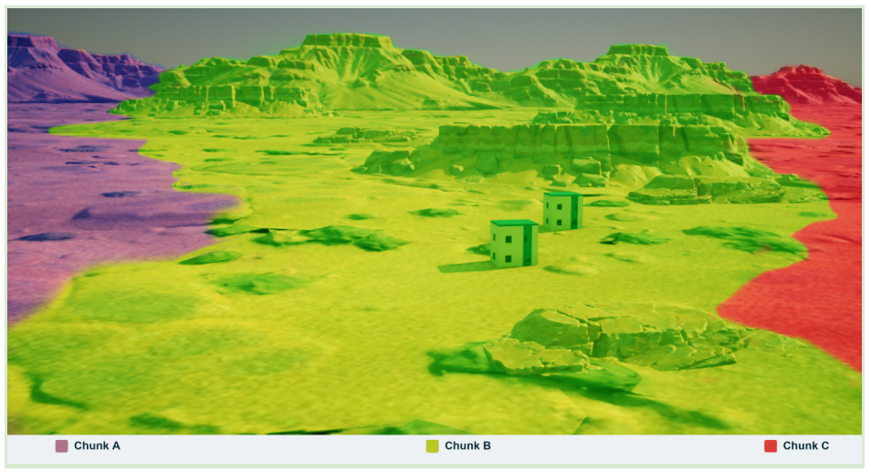
The grouping of these assets in bigger chunks can have an influence on how efficiently the background will be rendered. In wide backgrounds, Vista geometry can be separated into slices around the playable area, almost like slices of a pie. In this case, what really matters is how useful spatial division will be, not the exact form of these slices.
For instance, if all of the distant background is combined in one giant mesh, even its tiny visible part won’t let the engine cull this mesh. Spatial division will let the engine cull every chunk separately as the camera rotates and different parts of the background fall out of the visible area. This allows the background to stay visually large without every part of it remaining equally expensive at runtime.
Four types at a glance
| Content type | Authoring strategy | Optimization strategy |
| Large | Reusable tiled textures, multiple materials, detailed geometry | Switch to a simplified LOD with one material and baked texture |
| Medium | One asset, one unique texture set | Remove geometry as details stop contributing |
| Small | Collections sharing an atlas and material | Merge locally, cull with distance and reduce on lower-end devices |
| Vista | Simple assets sharing common materials and textures | Group into larger, visibility-friendly spatial chunks |
Optimize the Environment, Not Just the Assets
Optimizing individual assets controls their rendering cost, but it doesn’t guarantee that an entire environment will meet its performance target. If too much content is visible at once, the scene can still be expensive to render.
Plan Visibility While the Layout Is Still Flexible
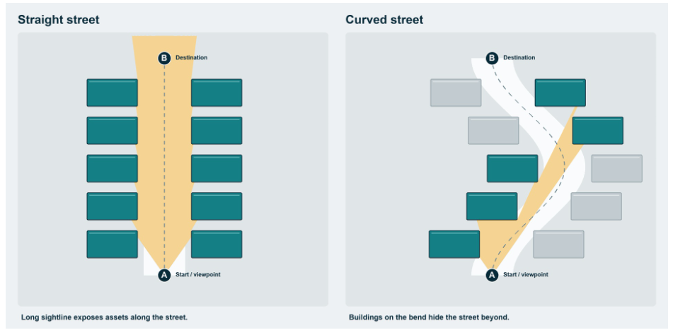
Visibility had to be considered while the layout could still change. It was much easier to address these issues early than after an environment was complete. Open spaces were particularly challenging because the camera could see a large portion of the environment at once.
Wherever possible, we looked for natural ways to break up sightlines. A building could conceal the next part of the map. A street could curve instead of exposing several blocks at once. A tunnel, hill, or change in elevation could hide parts of the environment the player didn’t need to see yet.
These elements still had to support gameplay and composition. We weren’t adding arbitrary walls purely for optimization; we were identifying opportunities within the level design to limit how much of the world needed to be visible at any given time.
Visibility also influenced decorative density. Open areas exposed more geometry at once, so they generally needed fewer secondary props and fine details. Enclosed spaces, where surrounding geometry naturally blocked parts of the environment, allowed for greater visual density.
Unreal Engine’s Precomputed Visibility feature may prove effective in some cases within appropriate mobile game development processes, specifically in scenarios where environments remain largely unchanged. However, the designer must ensure that there are elements within the layout that would allow hiding pieces of the scenery. The broader lesson is that visibility is a level-design problem as much as an asset problem.
Choosing the Proper Module Size
Modularity requires the same kind of balance. On one hand, larger modules can decrease object counts and, depending on material and section organization, can have less overhead for render times than creating a surface using a vast number of tiny modules.
However, there is a practical limit. In Unreal, selection of LOD for Static Mesh is based on the screen space size; hence, an overly large module will continue being in the higher levels of LOD for longer than necessary. You can compensate by pushing the LOD thresholds more aggressively, but eventually, a module may simply be too large to give you useful control over LOD transitions and culling.
The modules should be large enough to reduce wastage due to fragmentation but not so large that you lose useful control over LOD transitions, culling, or production flexibility.
Judging the Effectiveness of Optimization Using the Game Camera
None of these choices should be considered in isolation either. What matters is configuring your game camera, setting up a realistic resolution, choosing realistic target hardware, and examining every single resource through these eyes.
A low-resolution version of some distant level of detail might seem quite poor quality once viewed from the Static Mesh Editor, but if this level of detail covers no more than dozens of pixels on a cell phone screen, there is nothing wrong with that particular LOD. The issue is with judging resources on too large a scale compared to the actual context of their application.
The very same principle goes for setting up LODs, draw distances, and all kinds of visual performance expenses: push them aggressively, then move them back only as far as necessary for the transition to stop being distracting during normal gameplay. Spend lightmap resolution where the resulting lighting detail can actually be perceived.
Dialing Down the Scale on More Budget-Conscious Hardware
In case of more budget-conscious hardware, remove the least important visual information first: reduce small dressing, shorten draw distances, simplify Vista content, and simplify expensive materials and shadowing where appropriate.
There are several features available via Unreal Engine’s Device Profiles and scalability systems that allow setting up scalable options to tweak the rendering settings in accordance with different hardware. It is essential to maintain a sufficient amount of visual cues that will represent the environment and not switch off some random features until getting the required performance.
In each of the four aforementioned categories, the primary target was not to minimize every asset individually but to reduce the costs of visual information provided as long as the player is no longer benefiting from them.
The bigger assets will get reduced in detail of materials and geometry the further away they are from the player. Medium-scale assets will be missing the second layer of geometry. Small dressing can disappear entirely. Vista assets will remain significant, yet built from simple geometrical forms.
All the choices have been made taking into account how they will look through the game cameras on the chosen hardware in the context of the whole environment. That is how we spent performance where players could actually see the difference.
(Photo by Steve A Johnson on Pexels)


